I have to start by saying the basic information give in this article has been freely available from Austin 7 sources elsewhere. My method is a development of original work by Graham Macintyre.
I have not included any instructions for stripping and reassembly of the dynamo, as this information is freely available elsewhere. However, I would stress that the dynamo to be converted from 6 volts to 12volts must be completely sound.
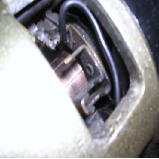
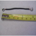
Graham’s method involves the removal of the “third brush” completely from the Austin 7 dynamo, and the connection of the third brush lead to the dynamo “earth brush”. I connect the third brush lead to it’s brush box terminal as originally wired. I then use a link lead to connect the third brush lead to the earth brush box.
The first picture shows the third brush [the thin brush] box with the brush and spring removed. The link cable in the second picture has been connected between the third brush box terminal and the earth box terminal.
Connecting an ohmmeter across the field connection lead and earth on the dynamo body, shows a resistance of 1.6 ohms. In this state the field will draw a current of 8 amps when working at 12volts. This value is much too high, and can be reduced by adding a resistor to the field lead. 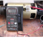 I have made the extra resistor from a coil of resistance wire taken from the heating element of an electric fire. These elements are readily available from electrical repair shops. The combined resistance of the dynamo field 1.6 ohms, plus the extra resistance 3.4 ohms gives a total of 6 ohms. This will give a field current of 2 amps when connected into a 12-volt system. These are the values used by Lucas on two brush 12-volt dynamos. You will have to experiment with the length of the resistance wire to produce the correct value. I wrap the resistance wire around a 5/16 BSF thread to form the coil. Six to seven coils are about correct. I have used a three terminal connector block to replace the original two terminal standard fitting. The left terminal connects the yellow “D” lead from the control box to the dynamo “D” internal lead. The right terminal connects the green “F” lead from the control box to the to
 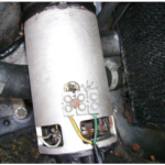 the extra resistance. The centre terminal connects the extra resistance to dynamo field internal cable.
The control box I use for the conversion is a Lucas RB 106. These units are easily obtained from autojumbles and Ebay. I prefer the early type that uses screw connectors. If all you can find are the later type with blade connectors these will work fine but do not look as good. Generally the RB 106 is very robust and does not give problems. However you need to remove the cover to examine the inside 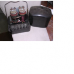
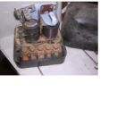
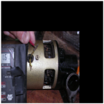
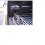 as there can be problems. The last picture shows the RB 106 in place of the original 6 volt Austin 7 cut out. The terminals on the RB 106 are marked; “E” earth connection; “D” lead from dynamo D terminal and the out lead from the ignition warning lamp; “F” lead from dynamo F terminal; “A” lead from A terminal on the ignition/lighting switch. “A1” not used. Having wired the RB 106 in, we now need to consider which parts need to be changed to suit the new 12 volt system. All bulbs including the ignition warning lamp will need replacing, as will the ignition coil. The original 6 volt starter motor will work happily at 12 volts. If you have an original Rist or late Ruby horn, these will also work on 12 volts. Any other type will need to be replaced. The electric wiper motor is best replaced, although the 6 volt one can be adapted. A bit too complicated for this description. For the fuel gauge system, a 72 ohm 1/2 watt resistor should be fitted between the ignition feed into the fuel gauge and earth. This has the effect of splitting the 12 volt supply in half, 6 volt to the fuel gauge and 6 volts to the resistor. You should be able to get a resistor from an electrical repair shop or Radio Shack. The resistance value is not critical; anything between 65 and 80 ohm will do the job.
.

